HOW-TO: PCB Trace Repair With a Wire Jumper Thru Board
Note: This guide is based on the IPC 7721 4.2.5 standard. Purchase the full standard from the IPC organization. The graphics and text have been created to provide easy-to-use instructions. Any content that diverges or supplements the IPC standard with be noted on the graphics, and text will be blue.
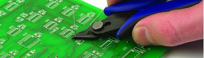
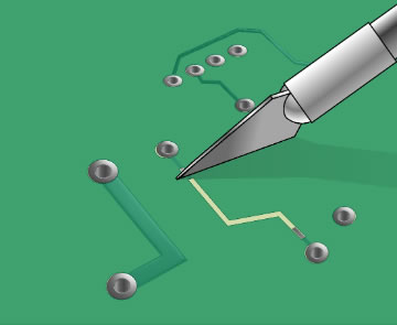
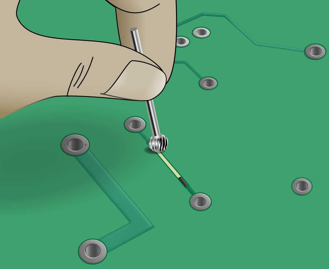
Step 1: Scrape away resist from repair areas.
|
Scrape away resist. |
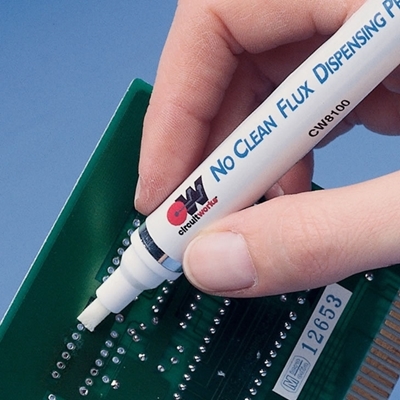
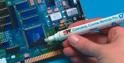
The damaged trace should be cut away and removed using a cutting tool, being careful not to damage any surrounding traces, components and contacts. Whenever possible, this repair should be made at least three millimeters away from contacts that will later be soldered in order to minimize the chance of reflowing the repair. Before pulling off the damaged trace, double-check that your cut is complete. Otherwise you risk lifting up the remaining trace and/or contact. Before you can add a jumper, the conductive surfaces must be exposed at the point of the break. You can use the cutting tool to carefully scrape away at least 3mm length of the overcoat material. A rotary tool grinding bit, held in your hand, is a good tool to gently scrape away resist in a controlled way. Make sure to scrape lightly to avoid damaging the conductive material of the trace underneath. Use an alcohol cleaning wipe, solvent cleaning pen, or some other method to remove overcoat particulates and other residues from the repair area. |
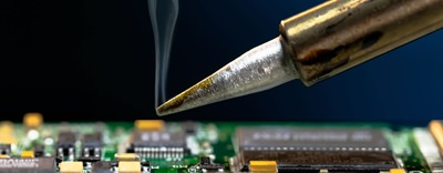
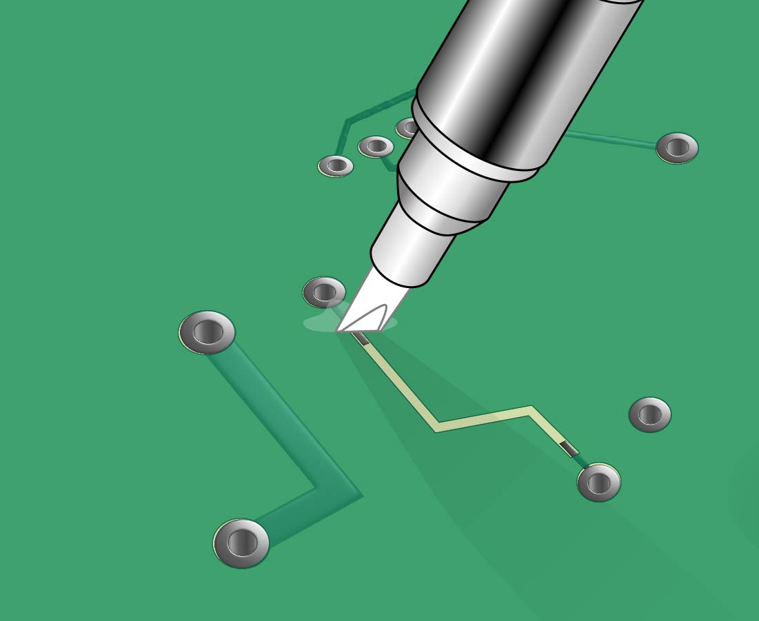
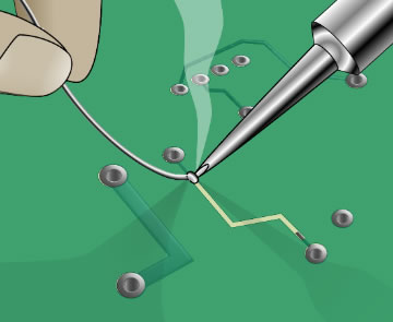
Step 2: Clean and tin exposed contact areas.
|
Clean off resist particulates.
Solder one end of jumper. |
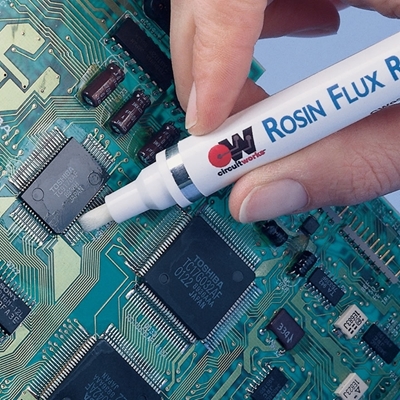
Apply flux to the existing traces, and use a soldering iron and solder wire to tin each end of the trace. Desoldering braid may be used to remove any excess solder. Clean the area again. |
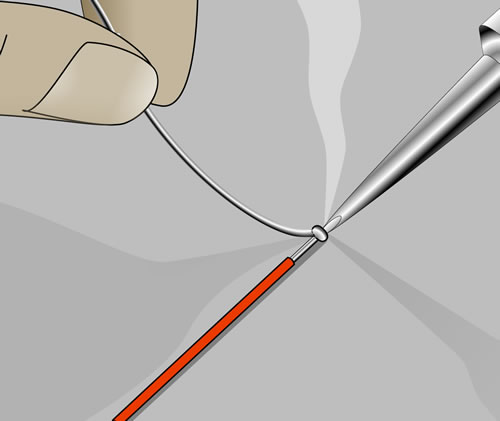
Step 3: Choose a strip of wire to replace the conductor.
|
To choose the correct sized wire to replace the conductor, use this table to match the trace to the equivalent solid wire diameter: Table 1 - Solid Wire Equivalents
|
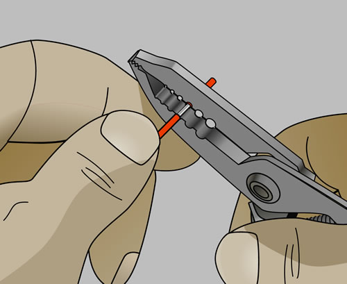
STEP 4: Strip and tin each end of wire jumper.
|
Strip insulation from ends of wire jumper.
Tin each end of wire jumper. |
Remove insulation from the wire ends if applicable, and tin the wire ends with solder. |
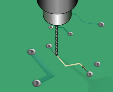
STEP 5: Drill through board next to conductors.
|
Drill through board. |
Drill through board next to conductors. The hole should be slightly larger than the wire diameter. Be careful to avoid any internal or external circuits. Clean the area as needed. |
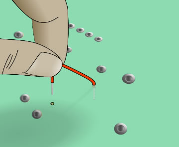
STEP 6: Feed wire through holes.
|
Feed wire. |
Feed ends of wire through the holes. |
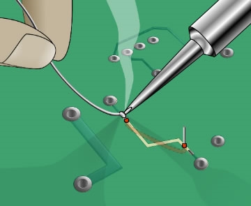
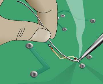
STEP 7: Bend wire and solder.
|
Solder ends of wire jumper.
|
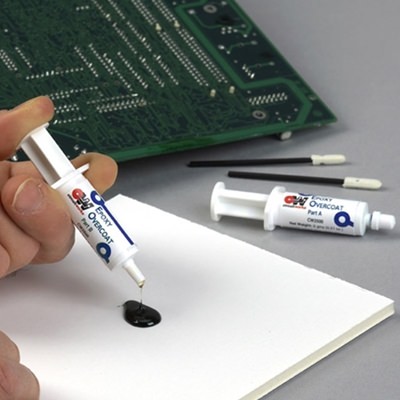
Bend the wire over the prepared conductors and solder each end of the wire. Overlap the ends of the new wire over the existing trace by at least twice the width of the trace. Apply flux to the overlapped wire and trace and solder them together. Clean and inspect connections. Epoxy or a coating pen may be used to protect the connections. |

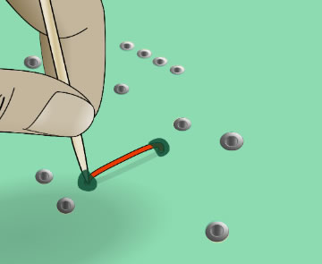
STEP 8: Secure wire to back side of the board.
|
Secure wire. |
The wire may be adhered using tape dots, epoxy, or adhesive. |
Tools & Materials
- Cleaner like flux remover pen or alcohol pad
- Jumper wire
- Epoxy overcoat
- Desoldering wick
- Knife
- Wire solder
- Soldering iron with tips
- Shear cutter
- Wire stripper
- Wire guide tool
Ask A Technical Question
Stay up-to-date on Chemtronics news, products, videos & more.
Related Products