CASE STUDY: Using Freeze Spray to Bring a $10M System Back to Life
Parts fail and electronics break. Good design practices can avoid some component failures, but many are unavoidable. Identifying the offending component and why it might have failed is the first step in refining the design and increasing the reliability of a system that experiences repeated component failures.
There are numerous reasons why components fail. Some failures are slow and graceful, offering time to identify the component and replace it before it fails completely. Other failures are rapid, severe, and unexpected.
Some common reasons for components to fail include:
- Aging
- Connection failures
- Overcurrent
- Over-temperature
- Overvoltage
Component failures usually follow a trend. In the early life of an electronic system, component failures are more common, and the chance of failure drops as the components are used. The reason for the drop in failure rates is that those components with packaging, soldering, and manufacturing defects often fail in the first minutes or hours of device life. This is why many manufacturers include a several hour burn-in period for their products. This simple test eliminates the risk of a bad component slipping through the manufacturing process, resulting in a broken device within hours of purchase.
Repairing a $10 Million System with Chemtronics Freeze Spray
Repairing a fault in complex electronic circuits can be a challenging task, but there are several steps you can take to troubleshoot and fix the problem.
To identify the problem, freeze spray for electronics can be used. Spray cooling of electronics using the circuit board cleaning spray to cool down components on a circuit board, which can reveal overheating faulty components allowing you make circuit board repair.
In addition to identifying faulty components, freeze spray can also be used to test the thermal properties of electronic devices. It can be used to check the cooling efficiency of heat sink or to see how a device reacts to changes in temperature. Overall, electronic freeze spray is a useful tool for troubleshooting and repairing electronic circuits.
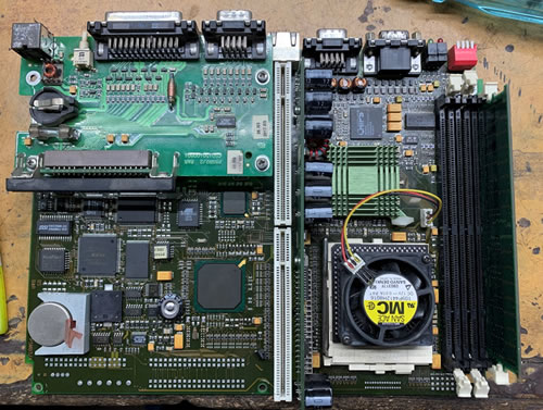
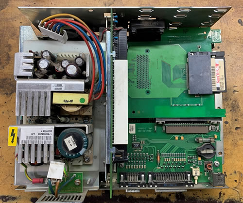
Test Case: We received a system (“Raising Machine”) from a textile industry in which SCADA was running to control the process. The technical team who separated it from the machine brought it to us and said it was not booting; a blank screen appeared on the screen instead.
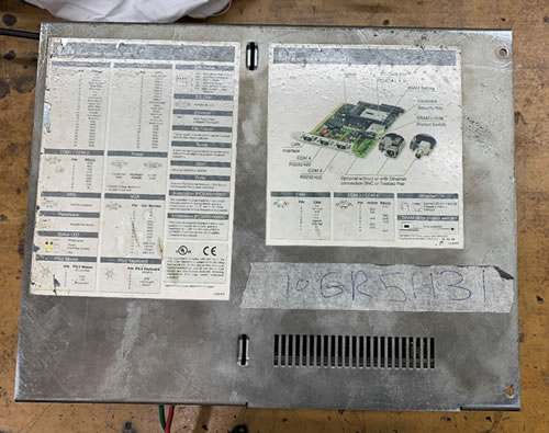
Privot 5000 System by Rockwell Automation
1. Identify the Symptoms of the Fault
The first step is to identify the symptoms of the fault. There are several symptoms that can indicate a fault in an electronic circuit including:
- The circuit isn’t functioning as intended
- Intermittent or sporadic operation
- Visible damage or discoloration of components
- No power or low power output
- Excessive heat generated from certain components
- Unusual noises or smells from the electronic device
- LED's or display not working properly
- Sparks or smoke coming from the device
Test Case: When powering the Privot 5000 system I noticed that the red led was constantly on, which is a temperature alarm. With such an alarm, the system would not boot. After studying the manufacturer’s manual, this temperature alarm could be from the Processer, I/O card, or from the display which could be transmitted by RS485. In our case it was more likely the CPU as the display was not attached and the I/O card was clear
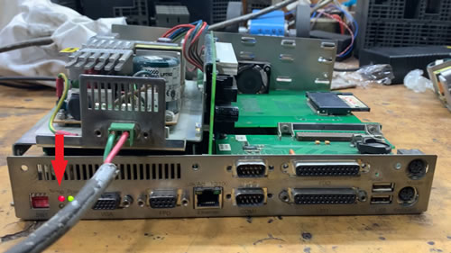
Temperature fault restricted the system from booting.
2. Check for Visual Signs of Damage
Look for any visual signs of damage, such as a burned component or a broken trace on a printed circuit board.
To check for visual signs of damage in an electronic circuit, you should first look for any physical damage, such as broken components or charred areas.
- Check for any signs of overheating, such as discoloration or melting of components.
- Look for any cracks or damage to the PCB board.
- Check for any missing or bent components.
- Look for any signs of corrosion or rust on metal components.
- Check for any signs of moisture or water damage.
- Check for any signs of overheating such as burnt smell, melted components and discoloration.
- Identify any components that appear to be missing or out of place.
Any of these may indicate that the circuit has been damaged and may need to be repaired or replaced.
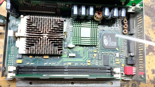
Test Case: Visually I found no signs of damage to any wire or connection and there was no sign of burning or melting from any components that might cause the temperature alarm in the system, so let’s move toward the next step of diagnosing the fault.
No visual sign of damage on the board
3. Apply Chemtronics Freeze Spray
Electronic Freeze spray is a diagnostic tool that can be used to identify intermittent faults in electronic circuits by temporarily altering the temperature of components. Here are the steps to apply freeze spray on an electronic circuit.
- Power off the circuit - Before applying freeze spray, make sure that the circuit is turned off and unplugged to avoid any potential hazards.
- Locate the suspected component - Identify the component or area of the circuit that you suspect may be causing the fault.
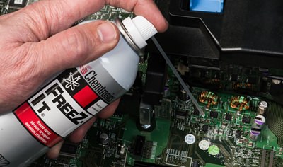
- Apply the freeze spray - Hold the freeze spray can approximately 4-6 inches away from the component and spray the area for 3-5 seconds. Be careful not to apply too much, as this can damage the component.
- Observe the circuit - Observe the circuit for any changes in behavior or symptoms, such as changes in voltage or resistance. If the fault is intermittent, it may only appear when the component is cold.
- Repeat the process - Repeat the process on other components or areas of the circuit, if necessary.
- Power on the circuit - Once you've finished testing, power the circuit on and test again to ensure that the circuit is functioning properly.
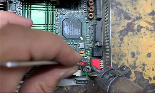
Test Case: As the issue was a temperature fault, it might be near the CPU which has a built-in temperature sensor. It’s a complex circuit which includes a lot of SMD components. It is difficult, hectic, and time consuming to test each and every component with an SMD Tester. Therefore, freeze spray was applied to the suspected area. The frost helped power on the circuit, and where the ice melted first identified the likely defective area.
Applying freeze spray to the board
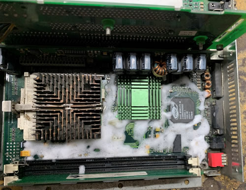
After 5 seconds of applying freeze spray, the frost rises.
4. Isolate the Fault
Once you have identified the symptoms and any visual signs of damage, you can start isolating the fault by disconnecting and reconnecting various components to see if the problem persists. Isolating a faulty circuit from the rest of an electric circuit is an important step in troubleshooting and repairing the problem.
- Identify the circuit - Clearly identify which circuit you need to isolate by studying the circuit diagram or schematics.
- Disconnect power - Turn off and unplug the power supply to the entire circuit to avoid any potential hazards.
- Test the disconnected circuit - Test the disconnected circuit using a multimeter to confirm that it is isolated from the rest of the circuit.
- Isolate the specific component - Once you have isolated the entire circuit, you can further isolate the specific component that is causing the problem by disconnecting it from the circuit and testing it individually.
- Label the disconnected circuit - Clearly label the disconnected circuit to prevent any confusion when it is time to reconnect it.
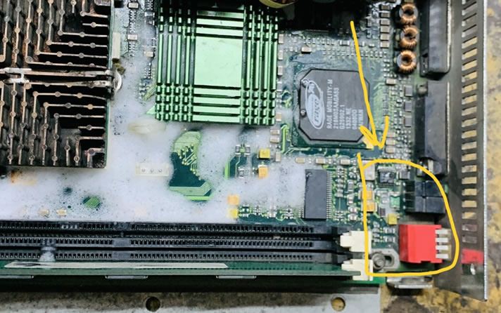
Test Case: After engaging the power supply, the ice started melting from the right side of the PCB board. I marked that area and powered off the circuit. I found that the two 1K resistors were short circuiting, leading to additional current, and resulting in excessive heat and eventually the temperature alarm.
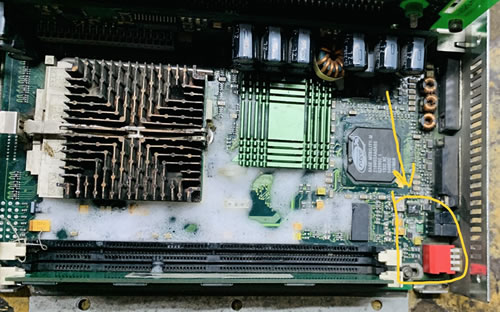
Suspected area of fault
5. Test Components
Test individual components with a multimeter or other testing equipment to check for continuity, resistance, and voltage. Testing an electric component in a circuit involves using a multimeter to measure the electrical characteristics of the component, such as resistance, voltage, and current.
- Power off the circuit - Turn off and unplug the power supply to the entire circuit to avoid any potential hazards.
- Identify the component - Clearly identify the component you want to test in the circuit.
- Set the multimeter to the appropriate setting - Set the multimeter to the appropriate setting for the measurement you want to take, such as resistance (Ohms) or voltage (Volts).
- Measure the component - Touch the probes of the multimeter to the appropriate points on the component to take the measurement.
- Compare the results to the specifications - Compare the results to the specifications provided in the component's datasheet or manual to see if it is functioning within the expected range.
- Repeat the measurement if necessary - Repeat the measurement if necessary, or test other components in the circuit as well.
It's important to follow the proper safety precautions when working with electrical circuits and components, and make sure to use the right setting on the multimeter to avoid damage to the component or the multimeter.
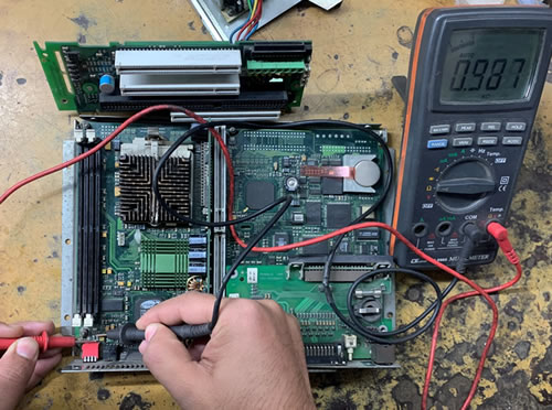
Testing the components of marked area with multimeter or SMD tester.
6. Replace or Repair Damaged Components
If a component is found to be damaged, it will need to be replaced or repaired. When replacing damaged components on an electronic circuit, it is important to first identify the specific component that needs to be replaced. This can typically be done by using a multimeter to test continuity or by visually inspecting the circuit board for any obvious signs of damage.
Once the damaged component has been identified, it is important to ensure that the replacement component is an exact match in terms of both type and specifications.
Carefully de-solder the damaged component, then install the new component, making sure to properly align and solder it. Double check the circuit board to ensure that there are no bridges or other issues that could cause further damage. Finally, test the device to make sure that it is functioning properly.
Test Case: The two 1k resistors were shorted, and were replaced with new resistors with help of a heat gun and flux.
Replacing the SMD resistance with the help of hot air gun.
7. Reassemble the Device
After all repairs have been made, reassemble the device and test it to ensure that it is working properly.
Reassembled device ready for service!
RESULTS
Electronic repair can be a complex process, but when successful, it can lead to the restoration of a device to full functionality. This can save money on replacement costs and reduce electronic waste. Additionally, successfully repairing electronics can also increase their lifespan, leading to a more sustainable use of resources.
In some cases, electronic repair can also uncover underlying issues that may have been causing damage to other components, further increasing the overall health and longevity of the device. Overall, successful electronic repair can result in cost savings, environmental benefits, and extended use of the device.
Test Case: After repairing the device, the system was rebooted with no temperature alarm. It was fully cleaned, reassembled and tested with an LCD display. The system worked as expected with no alarms.
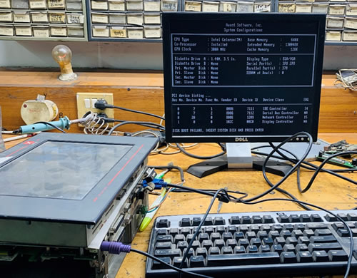
The system working properly in half-hour test.
8. Document the Repair
Document the repair process and the parts used to make it easier to troubleshoot in the future. Keep in mind that complex electronic circuits can be difficult to troubleshoot and repair, especially if you are not familiar with the specific device or circuit. In such cases, it may be best to consult a professional or refer to the device's manual for guidance.
A simple and cost-effective product, freeze spray is to-hand in every electronics store or shop and can have profound impacts on diagnosing and repairing failing electrical components to ensure a long device life and efficient processes. There are a variety of electronic spray cleaner products, and you may find it helpful to have several to hand for specific use-cases, whether it is pin-point accuracy, low global warming, or engineered for static sensitive device repair.
Browse Chemtronics selection of Freeze Spray or use the Selection Guide to find the products that meet your needs. Contact us 770-424-4888 or [email protected] for a technical consultation on the best freeze spray for your application.
Required Tools:
- Freeze spray
- Protected power supply source board.
- Multi screwdriver set for opening the system.
- Tweezers to pick up the components.
- Multimeter for testing the components.
- Hot air gun for soldering and desoldering.
Ask A Technical Question
Stay up-to-date on Chemtronics news, products, videos & more.
Related Products